So Your Office wants to Use VoIP, eh?

The Telephones, They are a Changin’

Back in the 70s and earlier, offices were served by a system with the telephone company providing all the connections, and forcing the use of their equipment. In the office where I worked, it meant 4 separate lines, and every phone had four lighted buttons. If a button was lit, that line was in use. If you pressed a button for a lit line, you joined the call. If you put a line on hold, the button would blink.

In the 80s, more and more companies installed their own private telephone switching systems, or PBXes. This allowed the customer to rent a fixed number of lines that came into their own equipment, and their equipment would divide up the lines, manage directing calls, sharing calls, and optionally policing what kind of outgoing calls could be made.

Plain Old Telephone Service

All of these implementations were referred to as “Plain Old Telephone Service” or “POTS”. In fact, even today, what are referred to as landline telephones, are often implemented as POTS at the customer’s site, even though some high tech network method brings it to the home (for instance, fibre optic cables). FAX machines are a good example of devices that almost always use POTS. In fact, where digital phone networks are in place, a device called an “Analog Telephone Attachment” or “ATA” can be installed to connect to a POTS device.

The Rise of VoIP

In the 21st century, a new technology called “Voice over IP” or “VoIP” came onto the scene. The idea wasn’t new, it’s simply digitizing audio and putting it over data networks. In fact, the telephone companies have been doing this, at least conceptually, in various ways at least since the 50s, including using “frequency division multiplexing” or “FDM”. With the rise of the “Internet Protocol” or “IP” in the 70s and 80s, and the rapid expansion of such IP network capacity in the 90s, the Internet now has the capacity to reliably carry many individual telephone calls… hence the popularity of VoIP.

Use of VoIP

Generally, VoIP is just like POTS. It differs in the way that the sound gets transferred between the end points. In IoTS, the sound is converted to digital messages that are put out over an IP network, often (but not necessarily) the main Internet itself.

Enter VoIP

VoIP comes in several different flavours, each providing a mix of features and capabilities. Sometimes, VoIP is implemented directly from one computer to another, but more often, some kind of exchange is used. This allows a VoIP user to contact any one of the other users on that same exchange.

More often, users of VoIP phones want to connect to regular telephones. For that, a gateway is required. Sometimes even the telephone company will provide such an gateway. Others are available, often for astoundingly lower cost, such as the one I use, VoIP.ms.

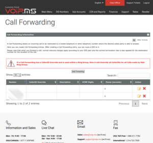
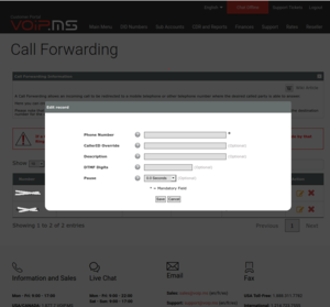
Relaying a Call to a “Regular” Telephone

It is possible to have a VoIP system transfer or relay the call back to the POTS system and ring an actual phone number (mobile or landline). Note that when a VoIP system relays a call, you will pay for both the incoming call and the outgoing (relay) call – each one might be pennies per minute, but if it happens often and lasts long, it can add up.

VoIP Reliability

VoIP can only be as reliable as the data network it communicates over. If that data network goes down, there is no VoIP. If the connection is critical, for instance, for emergency calls, then each and every link in the network chain must be backed up for loss of power and potential disconnection (for instance, broken wires or underground lines dug up).

POTS Replacement

Traditional telephone companies have spent over a century improving their reliability, for instance putting battery backup in all telephone exchanges so the POTS system can work for days with the power out, and providing redundancy on links between exchanges. Our residential Internet service is generally not battery backed up, and therefore often is lost during a power outage.

Mobile VoIP

You can use VoIP to a mobile phone, using its data service. Here again, the VoIP is only as reliable as the data service. If the mobile phone is turned off, out of the service area, or in a “mobile service dead spot”, then there will be no VoIP service.

Note that sometimes data service will fail before actual mobile phone calling – so it may be possible to dial out using the phone (3G/4G/5G/CMDA etc) even though VoIP does not work.

Similarly, it may be possible to have the VoIP system transfer or relay the incoming call to your regular mobile phone number if VoIP is not functional.

Consult with Professionals

For these reasons, be careful in the implementation of VoIP where emergency calls are likely to be made, for instance with the elderly or those often requiring advanced care. Consult with professionals who specialize in telephone service. These days, the telephone company will often offer VoIP services, and they will understand this issue well.

Cost

For those who are used to the cost of a telephone company landline, the low cost of VoIP.ms can be astounding. For as low as 3 dollars (US) a month, you can move your landline number to VoIP.ms. One downside is that generally you have to pay for every minute of outgoing and incoming calls, but that cost is generally in the 1 to 2 cents a minute. It’s difficult to run the bill up past 5 or 10 dollars a month!

Interesting Possibilities

Some VoIP systems will allow many phones to ring at the same time, even very far apart, in an effort to get someone to answer a given call. The rules for which phones ring, and when, can be complex. For instance, this can be used in an office setting, where maybe some incoming calls, like from known clients in a database, will ring all customer service advisors at one time. If nobody picks up by the end of the second ring, subsequent rings can be made to every phone in the office.

Multiple Locations

Even more interesting, phones in another location can ring. For instance, if a company has multiple offices, all phones for all service advisors can ring… or ring twice in the local office, then the rest of the rings worldwide. Calls can be routed to different places at different times of the day or night. The possibilities are endless, depending only on the exchange software used.

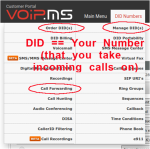
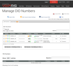
Finding You Whereever You Are

If you have a desk telephone with an assigned external number (referred to as “Direct Inward Dial” or “DID”), then with some VoIP systems, you can have your desk telephone, your computer, and your cell phone all ring at the same time, allowing you maximum flexibility. If you are away from your office, in an airport or coffee shop, you can take the call.

VoIP End Points / Telephones / Clients

What would be called a telephone handset in POTS, can actually be many things in VoIP:
– An actual telephone device or something that looks just like a telephone, in which case you might call it a VoIP telephone or VoIP handset.
– An answering machine, automated attendant, or artificial intelligence receptionist, in which case you might call it an end point.
– A program on a computer or mobile phone, in which case you might just call it an application or simply a client (as in client on the VoIP system). This is often called a “softphone” program.

In any case, each has slightly different character and options. I will use the most generic term “end point”.

Our company uses Dialpad, which is both a company providing an exchange and connection to POTS phones, and provides a softphone that appears to work well across VoIP handsets, computer and mobile phones.

VoIP Desk or Wall Mount Telephones

This type of an end point looks like a traditional telephone, but instead of a traditional telephone jack, it will have a network connection. Inside, it can be far more complex than a traditional telephone. I have used the Grandstream GXP1620, and can recommend it. These phones can be used very much like a traditional telephone, with all the features you would expect, and more.

In the office setting, there are extremely fancy VoIP desk phones. These actually look like small computers, and can be confusing to use. Just because a company can put fancy features into a phone, doesn’t mean that they should!

Real Traditional Desk or Wall Mount Telephones

A real traditional telephone can be used with VoIP, using an analog adapter. This adapter has a network connection on one side, and one or more POTS telephone jacks on the other. I have used the Grandstream HandyTone 286 and Grandstream HandyTone 486, both of which work very well.

The POTS jack on the analog adapter could theoretically be connected where the traditional telephone company’s wires come into a residence, thereby allowing the use of all the original telephone jacks around the house. This works well, as long as the number of telephone sets connected do not exceed the ability of the analog adapter to drive them with enough power. Be careful and test the setup – it can take too much power to ring old “analog” POTS phones.

Be sure to disconnect the telephone company connection before connecting the analog adapter to your in-house wiring. If you fail to do so, you may cause the telephone company trouble, and they will charge you money to fix it.

The Computer as a Phone

There are many softphone programs that you can run on your computer. Generally, this would require the use of a headset attached the computer (using speaker and microphone is generally bad office etiquette). A good quality headset is recommended, I have found the Mpow 071 USB Headset to be inexpensive (less than 30 dollars US) and good sounding, although be careful with it – it can be a bit fragile.

Softphone Programs on Computer

In an office environment, use the softphone recommended by the company.

In a personal environment, look into these, in no particular order:
Zoiper – I found Zoiper cumbersome to use, although many love it.
Linphone – Linphone is rudimentary and lacks features, but worked well for me on MS-Windows and Linux.
3CX – 3CX did not work well for me on Linux.
MicroSIP

As always, your mileage may vary. There are lots of lists of programs online.

VoIP on the Mobile Phone

There are lots of softphone apps for your mobile phone. Be wary of the app lists online – many include not-really-VoIP programs like Skype and WhatsApp, and mediocre or scam-filled apps as well.

Check Your Android Device, May Have Softphone Built In!

Earlier versions of Android had softphone capability built right in. This has the advantage of allowing the choice of using VoIP to dial out by default, or asking on every call. It also provides full integration with the phone’s address book, although other applications can sometimes do this as well.

Start the dialling program, touch the three dots in the upper right to drop the menu, select “Settings” and then “Calling Accounts”. If the option “Add Calling Account” exists, use that to add your VoIP system.

Softphone Programs on Android

In an office environment, it is generally bset use the softphone recommended by the company – unless you consider yourself an expert!

In a personal environment, look into these on the official app store for your device, again in no particular order:
– Zoiper IAX
– OpenPhone
– GroundWire
– Bria

In this case, I have no recommendation. It turns out that I used some of these programs long ago, but each one had some shortcoming that I could not fix. They may well be better now!

Again, your mileage may vary, and there are lots of lists of apps online.

Sound and Call Quality on Mobile Devices

Like most modern mobile phones and digital TVs, the call quality on VoIP is quite good. It can vary depending on the technology used in converting the voice to and from digital, but it should be at least as good as a POTS phone. However, like modern mobile phones and digital TVs, as they get poorer and poorer signal, sound will get weirdly garbled, choppy and distorted. This may happen even when you do not expect it, since the mobile data signal can vary rapidly from area to area, or even block to block.

You would not notice your Spotify or other streamed audio have trouble, because they are not operating in real-time. For instance, Youtube will often save up to a minute ahead on your device, so it can keep playing without interruption if data is completely lost. They are assuming that the data connection will be re-established within 30 seconds or so, then just start storing more, and you will never hear the difference.

However, for telephone conversations, we expect the sound to be available instantly, or at least within a very small fraction of a second. A few tenths of a second of delay can make it impossible to carry on a conversation. Telephone call audio is considered real-time. If the data gets delayed by a tenth of a second, it is just thrown away, because it hasn’t arrived in time to be useful.

This becomes important when we have a weak or intermittent data connection. The real-time requirement of the voice data means that lost data can’t be easily replaced, so depending on how the softphone deals with the missing or late data, the result can sound awful. Do not avoid VoIP for this reason, just know that when it happens, the mobile device is not broken, it’s probably the poor data connection.

VoIP Data Usage on Mobile Devices

Since the voice sounds on VoIP are converted to data and sent over the Internet, use of VoIP can eat into your monthly data allocation. If your mobile device is using local WiFi, then the VoIP data goes out on that, and doesn’t go on your data plan. However, in the absence of WiFi, then your data plan will be used by VoIP. The amount of data consumed by VoIP per hour depends on different factors, including the CODEC that the phone uses. A CODEC is the method that the sound is CODed into data and DECoded back to sound. There are many CODECs in use, some of which are faster, some of which use less power, some of which give better sound… but generally we just use whatever the default is for the softphone we choose. A brief review of available literature indicates that, in the worst case, a constant phone call over VoIP might use 30 to 400 megabytes per hour. In fact, you will probably find it to be a lot less, this is absolute worst case. For most people, unless they talk using mobile data for hours and hours a day, there will be no issue… but it’s not zero.

Battery Life for VoIP on Mobile Devices

In order to be able to receive calls at any time, the VoIP Softphone will generally contact the main VoIP server constantly. This eats some extra data on the data plan (although not that much, maybe a megabyte a day), but the bigger issue is its power consumption.

The computer chips at the heart of mobile devices spend most of their time in deep sleep, consuming as little power as possible. Those chips only transition to active mode when there is work to be done, like when the phone provider tells it to ring and advise you of an outside call, or when periodic check says there is a text message, or when the user is shaking, touching, or interacting with the phone in some way. Of course, there are degrees of operation, so the power consumption can vary depending on whether WiFi or Bluetooth is running, how bright the screen might be, and other factors.

When a program such as a VoIP Softphone is constantly running and checking for incoming calls, the chips don’t get to go to sleep… sometimes they never get to reduce power, consuming power at a significant rate, causing the battery to run down quickly.

Push Notifications

Most devices are on charge most of the time, and mobile batteries should be kept as close to full as possible to prolong their life, but it is important to know that the battery won’t last long when off of the charger, unless you can configure the softphone to use push notifications.

A push notification is a message that comes down, unannounced, from the server, waking up the softphone program and advising it that there is a call or message. If the server and softphone that you use can do this, then the phone can go back to spending most of its time in deep sleep, regaining your battery life. Push notifications are used by other programs like WhatsApp and Messenger for this reason.

Not all servers can do push notifications, but most of the big commercial servers can. Not all softphones can do push notifications, ask or check to see if they will.

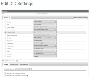
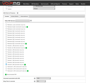
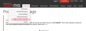
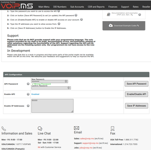
Information You need to Set Up Your VoIP Phone or Softphone

There are three key pieces of information that are required to set up a VoIP phone. Extra features, high security, complicated networks (for instance, behind firewall or router) can complicate this, but in general, here’s what you need:
– Internet name of the VoIP server, sometimes called Point of Presence or SIP Server – sometimes there is also a “secondary server” which is used when the first one is unreachable
– The user ID of the account, generally assigned by your system administrator and generally cannot be changed.
– The password to gain access to the account.

With these three settings, a client should be able to make and take calls.

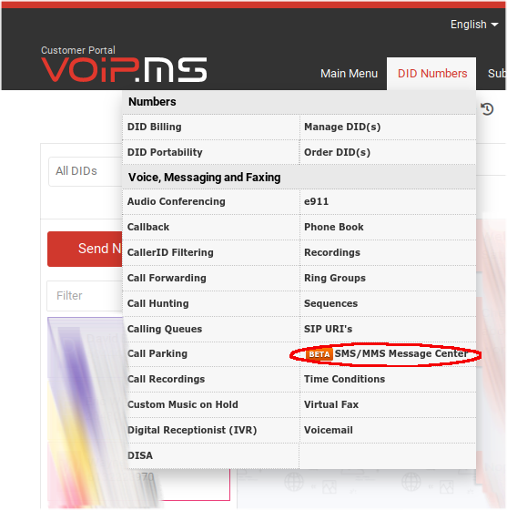
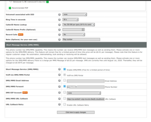
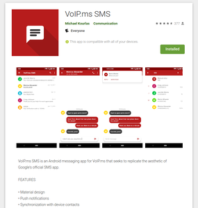
Text Messaging on VoIP

Text messaging (SMS or MMS) is possible on VoIP, depending on the capability of the client and the VoIP exchange/gateway used. For instance, on the VoIP.ms system, those numbers that are designated as “SMS capable” can send and receive short (SMS) messages, and in certain circumstances, extra-long messages and media (MMS) as well. Consult your provider.

Northern Zephyr… Implementing a new Board on Zephyr Project

We implemented a low powered battery operated product using LoRa. We implemented the proof of concept using the Ronoth LoDev board, then placed the main chip, the AcSIP S76S SiP, onto our own little board. Neat little chip! Oops, module. This neat little chip (there I go again) contains an STMicro STM32L073RZ ARM MCU, a Semtech SX1276 LoRa transceiver, and a +20 dBm power amplifier.

While I was working at Savoir-faire Linux, Jérôme Oufella suggested that I look into the Zephyr Project RTOS, which is a project of the Linux Foundation. Sure enough, both the STM32L073RZ MCU and the SX1276 transceiver are supported.

It was a pretty simple task, so I created a board support entry for the Ronoth LoDev in the Zephyr Project. Well, it wasn’t all that simple at first – the Zephyr maintainers had concerns about the way that I organized the files (rightfully so), and we took a long time reorganizing and refactoring the code. But in the end, I created SiP support for the AcSIP S76S chip (oops, module) and for the Ronoth LoDev board, and a few days ago, it was merged back into the master, yay! Here\’s the board documentation that I created… hmm there\’s a typo in there, grumble, will have to fix… some day!

Breathing New Life into Old SBCs with Real-Time Linux

While working at Savoir-faire Linux (SFL) in Montreal, I was commissioned to perform some Linux experimentation on an old SBC, using Buildroot, the PREEMPT-RT kernel build option, and FTrace. The first two articles have been posted on SFL’s web site – part 1 and part 2.

Although the work dried up and they let me go, I still believe in the folks at SFL and their work.

A new article was recently posted on Hackaday which discusses Real-Time OS basics, I recommend it for an interesting, short, read.

Texting Gone Wild

Long Text Messages

SMS text messages are historically limited to 160 characters (70 characters if in unicode). Years ago, devices would refuse to send a longer message, forcing users to break the message up themselves. These days, however, most devices will allow a user to create a much longer message.

So, what happens when you send a longer message?

There are two ways to handle SMS messages of excess length:
1. Split the text into multiple shorter messages, which might be reassembled into one message by the receiver, or might be presented as multiple messages. Each message is shortened by a few characters, to put in a reconstruction header that the receiver can use to put it together.
2. Change the text to an MMS message, which actually uses the data plan to communicate.

What is this MMS of Which You Speak?

MMS is an alternative texting data format that can also do images, sound files, etc. On most devices, if you try to send a text with a picture or other media file, the entire message is automatically upgraded to MMS. As mentioned, this uses the data plan to send the content, but uses the SMS channel to send meta-data that advises the receiving device to load the actual message using its data plan.

“Legacy” SMS Support on VoIP.ms

Up until August 2020, VoIP.ms did not support MMS. Neither did the two most common means of sending and receiving text messages on their platform. They do provide an API whereupon you can write your own interface (as Michael did for item 1 below).
1. The android application VoIP.ms SMS is an open source project developed by Michael Kourlas, an independent programmer. It only supports SMS, never has done MMS. Also, this application relies on his servers to transfer data – for which I am thankful, because I appreciate the service!
2. The “legacy” web application, has no MMS.

In both “legacy” programs,
1. If you try to send a long message, it splits it up automatically, according to the standard.
2. You can’t send any media.
3. If someone sends you a long text message, it’s a crap shoot – if it is split up by the sender, the pieces come through. If it isn’t split up, the message is just silently lost.
4. If someone sends you media, the message is just silently lost.

“New” MMS Support on VoIP.ms

Image of SMS/MMS Menu Entry
Per above, in August 2020, VoIP.ms started supporting MMS using a new web interface from the main page -> DID Numbers -> SMS/MMS Message Centre, or directly at the SMS/MMS portal. Here, you can do full SMS and MMS send and receive.

The new portal works reasonably well, but it has its quirks:
– It might display a green dot beside a person’s name if they send you a new message… but it takes a while, and it won’t auto update for you. You have to click on their name again, to get the message to appear.
– It appears that a refresh is required every night at midnight eastern time. To do this, click DID Numbers -> SMS/MMS Message Center and wait for the refresh.
– If clicking on the menu item doesn’t work, hit “refresh” in your browser. At times, this will cause a login prompt to be displayed. If you enter your login credentials and it does not appear to do anything, the site is probably doing reverse proxy check – press “return to main site”, login there, and click ID Numbers -> SMS/MMS Message Center again.

Now, can you use VoIP.ms as a “complete” alternative to your cell phone texting? Well… yes, and no.

Android Application Support

The Android app has been updated to support MMS. It appears to be quite reliable. Kick Michael over a bit of cash if you use it and it works well for you.

Not All Providers Can Send to VoIP.ms Text System?

Yes, if it works, then you are away to the races. I use it all the time to keep contact with folks in the US and elsewhere.

The interesting thing is that some texting systems will not send to VoIP.ms text system, not sure why. There is some kind of “provider matrix” used by each telco for delivery of their texts to another telco, and for whatever reason, VoIP.ms isn’t on some lists. For instance, my bank in the USA tries and tries to send SMS texts to my VoIP.ms number to confirm my login, but it never works. The telco automation provider Twilio sometimes has trouble too.

It all seems kind of hit-and-miss. Maybe harassing the VoIP.ms guys would get them to chase it down and get onto those “choice matrix” lists, but I have not tried.

Text Message Provider Matrix

This text message “provider matrix” thing has been around for a long time. Long time ago I found that every telco has an incoming E-mail to text message portal – and found out that you can just carpet bomb all of them with the telephone_number@each_telco. Those telcos who don’t have the specified number will silently ignore. By extension, connection between telcos is probably done the same way. If VoIP.ms were not on the list, then they would not get the message, and would not receive the text.

Other Means of Getting Your VoIP.ms Text Messages

You can also have text messages forwarded to a “real” cell phone, but you do have to remember if you reply that it comes from that “real” cell phone – so your correspondents will send to one number, get back from another. Worse if that number is out of country – you reply, it comes from your “real” cell phone, and you get charged for it.

You can also have incoming text messages bundled into an E-mail, but not sure how you would reply to that.

VoIP.ms SMS and Call Forwarding

So, here is how to set up VoIP.ms for SMS texting and call forwarding.

Important Term “DID”

The first thing to know is a specific term.  DID, or “direct inward dial”, is your telephone number that can be called.  In other contexts, it can mean the phone that will be connected to, when someone dials that number.  In our context, it will just be the number.

Why the distinction?  Outbound calls use a different system.  Simple as that.  Leave that for another time.

Follow the Money?

Bear in mind that, although the base cost for each DID is ridiculously low, nothing is free.  SMS texts cost something like ¾ cent each, inbound and outbound calls cost by the minute (something around 1 cent per minute).  I find this acceptable, because there’s no way that I could ever even come close to the cost of my old phone bill!

Accounting

OK, first thing is to create your account and fund it.  All amounts are in USD.  I would suggest using PayPal to fund it, and I’d suggest putting in US20 or US30 to start.  You can set an “alarm” on your account to send an E-mail when your balance falls below a certain amount.

Once you’ve got your account and it is funded, then for the task at hand, here are the main management menu items you will use.

Set Up Call Forwarding Target

First, set up a call forwarding target.  Select “Call Forwarding” and create an entry pointing to where you want calls to be potentially redirected to.  You can create more than one – you can select which one is the actual target, for each DID.

Here’s a sample entry screen.  You don’t have to touch anything else except to put the 10 digit phone number of the target to forward calls to.

Ordering Arbitrary DID(s)

If you don’t have any DID(s) yet, you will have to go to “Order DID” first, and create them.  The word “order” is a bit of a misnomer, because it’s all automatic and practically immediate.  You can create as many as you want, and it’s quick.  You can pick a telephone number in pretty well any area code in North America, and some numbers overseas.  Be conscious of their cost, they don’t all cost the same in monthly cost or in inbound & outbound per-minute charges.

Porting Your Number In

You can also “port” your existing number from a cell phone or landline phone carrier to VoIP.ms.  It’s a bit of a process – not that hard, you just have to read the procedure and go through the steps.  The telcos are anal about making sure you follow the steps – they are trying to prevent port-out fraud, which has happened in the past, with disastrous consequences – think “SIM hijacking”, not nice.  

Anyway, it is standard practice these days to set a port PIN on any mobile DID.  This is wise to do.  Be sure to keep it private.  If set, then without this PIN, port requests are ignored.  Of course, keep track of that port PIN, or else you won’t be able to perform a port either 😊   Keep these things in your password manager (use LastPass – don’t pass “go”, don’t do anything else – just do it).

When you port your cell phone number, be sure to indicate that it’s a mobile/cell phone.

Managing the DID Settings

Anyway, once you have any kind of DID in your account , go to “Manage DID(s)”:

On the left, under “Actions”, you will see three coloured icons – an orange pencil & paper (edit this DID settings), a blue paper with lines on it (read-only view this DID settings), and optionally a green cell phone, which indicates that this DID supports SMS & MMS.  

Click the orange pencil & paper icon, which should bring you to this screen:

Select “call forwarding”, and if necessary, drop the selection box and choose where to route the call.

Scroll down and choose the DID point of presence:

This simply is the Internet server location that you will connect to, when you come around to using a VoIP phone.  I would select one close to your primary use location.  You can change it later, but for your VoIP phone to work (inbound and outbound), your VoIP phone must point to the same server name.

Continue to scroll and you will see the SMS settings.  Above that are a few key settings related to the cost of calls, review each one.  

For SMS, you have to “enable SMS/MMS” and, if you want to SMS/MMS forward, to select this option and put the 10 digit target telephone number in here as well. 

The “SMS/MMS URL Callback” option is for use with the VoIP.ms Android SMS application, see below.  You can leave it unchecked, but the value should be “https://us-central1-voip-ms-sms-9ee2b.cloudfunctions.net/notify?did={TO}“, per below.

Save the changes, and it should work!

Installation of Android App to Support Near-Native Texting

There are a few limitations, but it works very well for me.  It’s how I keep in touch with my friends in Phoenix (and formerly of Phoenix 😊).  I ported my US cell phone number to VoIP.ms and use this app to text with them.

Here is the Android application:

Now, the difficult part – setting it up.  The app is open source, and its help page looks like this:

You have to enter that string into the DID\’s “callback” entry (see above),  then enable the API connection back on VoIP.ms, see below

Enabling the API Connection

From the VoIP.ms main page, select “Main Menu”, then “SOAP and REST/JSON API”:

Put in an API password (this will be what you give to the Android app, above), enable the API, and ensure that the “Enable IP Address” is set to 0.0.0.0.  You can restrict the IP address here, if it is well defined and won’t change.

LoRa, LoRa, LoRa!

Summary of Transceivers

Round 1

Reyax RYLR896 module (have 3 of them) – contains RYLR890 RF module (which apparently contains Semtech SX1276 RF chip) + STMicro STM32L151C8T6A MCU – has TTL async interface, so used USB to TTL serial to talk to it.  Reliable communications but weird, uses “AT” command set.  I see this as being a replacement for the EOL’d Linx Technologies FHSS radios on the RMM – but the command protocol is different, so I’d have to rework the Microchip PIC18LF4321 MCU code.  To replace the CM, I’d use this module and say the Silicon Labs EFM8UB2 Universal Bee to translate the weird commands to emulate the old Linx FHSS radio.  The EFM8UB2 has built-in USB interface, SPI, 8051 core, and lots more – I used it in the DC Module at ERLPhase, and I like the chip.  I have the dev kit for it.

Ronoth LoStick (have 2 of them) – contains Microchip RN2903 RF chip + USB interface.  I got them to talk to themselves, that was easy.  I’d love to use this to replace the Collector module, but it’s not clear how to get it to talk to the Reyax RYLR896, haven’t been able to make it work.  Its settings are very different than the Reyax RYLR896, so I haven’t been able to make them intercommunicate.  The internal design and internal software do not appear to be open source.

Waveshare SX1262 LoRa HAT for Raspberry Pi (have 1 of them) – contains EByte E22-900T22S RF module (which apparently contains Semtech SX1262 RF chip + not sure which MCU) also has USB interface that I used to talk to my computer directly to the EByte module.  This looks cool, has its own Wiki page describing it, and example code.  I modified a Python program to talk to it, but couldn’t get it to respond.  Tried all the baud rates, put a bunch of debug in there, just not responding… although I seem to see blinky lights saying that the RX & TX are working…

HopeRF RFM95W little LoRa module (have 2) – pretty small – almost small enough to use on a puck – castellated “postage stamp” SMT mount.  Apparently has an Semtech SX1276 RF chip inside – which should make it compatible with the Reyax RYLR896… it needs sync serial (SPI) and I have no easy way to talk to it.

Microchip (formerly Atmel) SAMR34 (have 1 DM320111 SAM034R Xplained PRO dev kit).  This is yet another architecture, contains a 32-bit ARM Cortex M0+ MCU and LoRa Transceiver.  I have not tried it yet.

Round 2

Seeed Systems Dragino LoRa/GPS HAT for Raspberry Pi has a HopeRF RFM95 (ordered 2 on 2020-04-11 – arrives in about 2 wks) (not “W” – not for North America) on it, but I plan to change it to my HopeRF RFM95W so can control directly from my Raspberry Pi through its SPI port.  This appears to be an open design with its own Wiki page, and there’s instructions on how to set it up to do LoRa on the Raspberry Pi, and Github code to do LoRa on the Raspberry Pi.  This LoRa/GPS HAT for Raspberry Pi also appears to be available from Antratrek in the UK.

Adafruit has a RFM95W LoRa Transceiver breakout board that would make it easy to play with the Hope RFM95W, but they are out of stock, Antratrek in the UK appears to have some.  There are similar products from Tindie and another one from Tindie.  Maybe I’ve got enough RFM95W options at present.

Ronoth  LoDev  ( Ronoth are the folks who made the LoStik).  It’s a bit newer than LoStik, appears to be a different focus.  It uses the AcSip S76S system-on-a-chip (which they call SiP – System in Package).   The S76S contains a Semtech SX1276 RF chip and a STMicro STM32L073x MCU.  It’s sold out at Ronoth, but CrowdSupply says they have some, so I ordered 2 pcs from CrowdSupply on 2020-04-12.

Round 3

I retrieved my personal Raspberry Pi 3 B+ from the office – where I had it placed to facilitate my staff being able to navigate to an important source scanning site from their homes – no longer required because the local IT folks spun up an Ubuntu virtual machine to use instead.  I put the Waveshare SX1262 LoRa HAT for Raspberry Pi onto my Raspberry Pi, and gave it a try.  Well, had to remove the Raspberry Pi from its nice little plastic Adafruit box, because the LoRa HAT interfered with the internal ribs.

Anyway, after some fiddling, I was able to get the first stage of talking to the LoRa HAT to work… but after ser.inWaiting() said there were characters waiting at the port, the subsequent ser.read() call caused an unceremonious abort.  No message, no nothing.  I wasn’t happy with this, but after playing around for a bit, I abandoned my efforts.  Oh, well.

So, overall with the Waveshare SX1262 LoRa HAT for Raspberry Pi , it seems that the mode pins are important and have to be twiddled in order for the board to work.  That’s probably why I couldn’t make it work on USB from my LINUX computer.  That’s a problem for another time, perhaps.

Round 4

Back to the Waveshare SX1262 LoRa HAT for Raspberry Pi .  With manually twiddling the pins, I can talk to the RF module in configuration mode, and got it to respond.  There seems to be a “temporary” configuration and a non-volatile configuration.  Even when I’ve written the parameters I want to non-volatile configuration, then unplug, switch mode bits to talk through the radio, and have the Reyax RYLR896 module chattering away beside it, I get nothing.

What I have is one Reyax RYLR896 module set as Network ID 6, Node ID 10, alternating transmissions to Node IDs 20 and 30 (yes, in decimal – I checked).  Then I have a second Reyax RYLR896 module set as Network ID 6, Node ID 20, receiving the alternate transmissions.  So, I set the Waveshare SX1262 LoRa HAT for Raspberry Pi set to what I think is the same frequency, and as Network ID 6, Node ID 30 (0x1E)… and receive nothing.

I’m not absolutely sure they are set to the same transmission parameters.  I see no way on the Waveshare LoRa HAT to set Bandwidth, Spreading Factor, Preamble, or Coding Rate.  Hmm, and the frequency is 850.125 MHz + ((0 to 80) x 1 MHz) – so I set it to 915.125 MHz.  Does the 0.125 MHz offset matter?  Argh!

The EByte E22-900T22S RF module , which is the RF module on the Waveshare LoRa HAT, has documentation which is rather sparse.  It documents only 9 registers to set (although it does show all the bit settings) from locations 0x00 through 0x08, and then another 7 bytes of identification at 0x80.  I cycled through the entire space from location 0x00 through then end of the identification.  I found several more non-zero values up to location 0x17.  Perhaps they hold the key to interoperation with the Reyax RYLR896… then again, maybe not.

Read out registers:
0x0000: 00 1E 06 60 00 41 00 00  00 00 00 00 22 14 16 0B
0x0010: 00 00 08 08 C2 03 01 63  00 00 00 00 00 00 00 00

0x0080: 00 22 14 16 0B 00 00

I went to the datasheet for the Semtech SX1262 radio chip that’s inside the Ebyte E22-900T22S RF module, just to see if maybe if I could infer more from that – if the existing E22-900T22S commands were reflected in the SX1262, there might be details of other commands.  Apparently not, the structure is completely different.  It makes sense, because the SX1262 communicates solely by SPI interface… and the E22-900T22S talks by async serial – so there must be a chip inside there to do the interpretation, and perhaps other things in the protocol.  I do seem to recall seeing something about this MCU, but from the Ebyte E22-900T22S documentation, it does not appear to be exposed to the outside world, so working on that could be a severely uphill battle.

Oh well, I’m honing my Python serial skills, and almost ready for the other modules to arrive – Seeed Systems Dragino LoRa/GPS HAT for Raspberry Pi should be here this week – the package is currently in Cincinnati, OH, at the DHL warehouse.  Apparently, the two pieces should arrive on Tuesday.  I hope so – I had to pay duties & fees on it 🙁    I will still have to switch the radio module on both pieces – although I might test it at the (wrong for North America) frequency of 868 MHz first.

The Ronoth  LoDev has not shipped from CrowdSupply after a week; I suppose that means that it’s not in stock in their warehouse…  or maybe this COVID-19 trouble has got them waylaid.  That’s unfortunate, because I see the S76S module on the LoDev as the ultimate long-term solution – it has the MCU on-board, I can program it, it has a good example, and can support USB – well heck, maybe the LoDev itself would be the CM replacement.  Anyway, it could work well in both the RMM and the remote in-the-ice measurement “puck”.

Next Steps

The RFM95W Approach

The Seeed Systems Dragino LoRa/GPS HAT for Raspberry Pi has the European frequency LoRa chip on it but the same footprint as the North American frequency HopeRF RFM95W module, which I have here.  I can switch the modules so that the unit is on North American frequencies, then put this onto the Raspberry Pi, load up the Github code to do LoRa and try to talk to the Reyax RYLR896.   I’m not sure if this will lead to a viable solution – it would be more economical to buy Reyax RYLR896 modules and add the EFM8UB2 Universal Bee to translate between the silly “AT” commands and the old Linx Technologies FHSS protocols.  I’d like to replace the STMicro STM32L151 MCU on the RYLR896 board, but the code doesn’t seem complete – looks like it might be a bear to get up and running… might be worth the trouble, if I could maybe just reprogram the STM32L151 MCU to do the whole job and emulate the Linx Technologies FHSS protocols directly (instead of “AT” commands).

The S76S Approach

Assuming that I can get the LoDev from Ronoth to talk, and can program the MCU inside of it, then I could develop a version that would emulate the old Linx Technologies FHSS protocols inside the MCU.  That MCU has USB capability, so it could be a single-chip solution for a revised Collector Module (CM) and still talk to the legacy MS-Windows software using this emulation.  On the other hand, it also has async serial capability, so it could be a single-chip solution to replace the Linx Technologies FHSS modules inside the Remote Measurement Module (RMM) without changing the programming of the Microchip MCU inside it, again using this emulation.  Thirdly, the S76S chip has I2C and SPI capability, and it’s tiny, so with a temperature sensor, it could become the basis of a new “puck” to be buried in the ice as well.

Common Ground between the Approaches

Since both the Reyax RYLR896 and S76S modules have the Semtech SX1276 RF chip inside, it’s also possible that they could both be interoperable with each other… although, based on my recent experience, I won’t hold my breath on that.  Having options is always a good thing!

Beating Up on Some Existing Ones a Bit More

I might work on the Waveshare SX1262 LoRa HAT for Raspberry Pi a bit more.  I seem to recall that I got it to answer to my settings etc., but upon further review of the Python code, maybe I didn’t 🙁  I should review again.

A second review of the Ronoth LoStik shows that its settings aren’t so much different than the RYLR896.  Maybe I need to revisit this one.

STMicro ST-LINK Debug Adapters

I’ve also got 2 different ST-LINK/V2 debug adapters – one “official” STMicro one, and one cheap knock-off (because it arrived quicker and was really inexpensive), so if I could figure out how to set up the whole STM32L151 development environment to reprogram the Reyax RYLR896, I could do that.

LoRa in Action?

The LoRa modules came in.  1 x Reyax RYLR896 Module, 1 x Ronoth LoStik USB LoRa stick.  I realized that I didn’t have any TTL level serial devices near at hand to talk to the RYRL896, so then I ordered 2 x Covvy CP2102 USB to 3.3V/5V TTL Serial devices.

There are some Python code examples available for the LoStik on github, so I snagged them and gave them a run.  The easiest one is to toggle the on-board LEDs, and that worked fine, but the transmit/receive didn’t do much of course, because I don’t yet have anything set up to transmit/receive with!  Sigh.

I did set up a Raspberry Pi 3+ to talk to the LoStik though – with WiFi access, VNC desktop, and full Python implementation.

Once the CP2102s arrived, I wired one up with the RYLR896, plugged it in, found out that it enumerated as /dev/ttyUSB0 on my system, and fired up minicom with the default settings of 115200 bps, 8/N/1.  Sure enough, I could get a response from the RYLR896, but it constantly said “+ERR=1” with every character.  I’m pretty sure that it timed out between characters.  Try as I might, I couldn’t get minicom to batch up the characters and only send when I hit <RETURN>.  Well, that and it was confusing on how to get <CR><LF> at the end of the line…  let’s see…  stty cooked </dev/ttyUSB0… what else???  Argh.

So I installed and tried puTTY.  It’s in the repos, apparently!  Wow.  Same thing, argh.

Then I tripped over this Youtube video showing use of the RYLR896, and it showed a terminal emulator called CoolTerm, available for LINUX, Mac and MS-Windows.  Sure enough, it’s the real deal, with a GUI, and the right options to allow “Line Mode”, Local Echo, and CR+LF on <ENTER>.  It worked!

The RYLR896 “AT” commands are case sensitive.

Now, to see if I can get the LoStik to talk to the RYLR896…

I’ve ordered a second LoStik and a SX12621 LoRa HAT for the Raspberry Pi.


Modern RF Communications Modules

Filipe and I have been looking into expanding and extending the Eye on the Ice(tm) system for Hans Wuthrich of Ice Consultants International.  The original system was developed around 2008/2009 by my team at Norscan Instruments Ltd., back when we were diversifying our product offering.  I was Product Development Manager with a fantastic group of very talented people working with me.   They did a great job of the design of the Remote Measurement Module (RMM), the Collector Module (CM), and the MS-Windows software that went with it.  It’s a great system!

Alas, RF modules eventually go obsolete, and the ones used in the Eye on the Ice system will likely soon be unavailable.  They might be around for a few years, who knows, but the writing is on the wall – technology changes, RF emissions regulations tighten, and products change.

Last fall, and into the new year, Filipe and I did a proof-of-concept for an in-ice Eye on the Ice sensor which would use Silicon Labs Zen Gecko EFR32ZG14, the Zen Gecko.  Although the system did work, we found that the low-level control of a mostly-asleep sensor was going to be a huge job.  The examples given, and the information provided, just weren’t enough to get us over the challenge.  In addition, the Z-Wave devices appear to “retry themselves to death” if the central station goes away – not a good thing for a low-cost, sealed temperature sensor device.

One thing that looks like an interesting alternative is the LoRa system – long range, low data rate, adaptable for different jurisdictions.  Probably an excellent alternative for transmission of data like Eye on the Ice.

There are modules available to test – look at the Reyax RYLR896 LoRa Module at Amazon, a LoRa Hat for Raspbery Pi at Amazon, a LoRa USB stick at Amazon.  There also seems to be a LoRa book, but it has bad reviews.

The Reyax web site has a few interesting LoRa modules.  Their modules use “AT commands” to set centre frequency, spectral parameters, and data rate.  With that in mind, these modules could almost be a drop-in replacement for the present Linx FHSS modules that Eye on the Ice uses!

The RYLR896 LoRa module from Amazon is documented here – along with specifications for the “AT commands”.  The board-mount module that it’s based on is the RYLR890 which is documented here.

The MicroChip (formerly Atmel) LoRa offerings are also interesting.  There is the R34, a low cost BGA SoC that has a 32 bit ARM plus a multi-band LoRa radio.  It’s available on the cool DM320111, a US$99 reference design / development kit, also available from Amazon for the same price.  One concern is that the documentation talks about the LoRaWAN protocol stack, which we’d want to turn off, so we can just talk simple serial from station to station.

Then I found the Hope RF series of LoRa modules, very interesting, especially the RFM95W.  It looks like it’s just what we need.  It does simpler modulation as well, just by flipping a bit in its configuration.  You would lose all the error correction hyper sensitivity, and built-in spread spectrum, but it would be an easy way to establish simple communication. There seems to be plenty of documentation on the chip, the RF95.  If you Google “HopeRF RF95”, you will find RFM95_96_97_98W.pdf on the SparkFun web page, which gives comprehensive documentation of the chip, its operation, and its registers.  I suspect SparkFun stocks, them, and Digi-Key has them as well.  There appears to be a nice Demonstration Kit, the RFDK_RFM95, but I can’t seem to find a vendor…  GorillaBulderz in Australia lists them but has no inventory, and no indication of when it will be in stock.

OK so maybe it was IRIG madness… (not so much LCD madness)

I’ve been playing, on and off, with IRIG-B decoding – first, modifying NTP source code to continuously dump decoded data from what it reads on the audio input port… then extracting the IRIG-B decoding code to a stand-alone program which would read from the audio input port and output decoded data… then added unmodulated IRIG-B decoding (which was a challenge, due to audio bandpass limitations, but I made it work)…  then putting it to an LCD display, then another, then another with keypad…

Through it all, I struggled to find a practical way of making it useful.  After a discussion with Norbert of ERLPhase, I think maybe we came up with something.

Mobile Device Use?

Rather than expect someone to load up LINUX onto their laptop, drag the laptop to the site where the IRIG-B source is, and use a special cable to connect to the audio input port… why not use the mobile device that everyones seems to carry around with them?

I briefly tried to capture the IRIG-B signal (modulated and unmodulated) into a mobile device, without success 🙁    I tried both my Samsung Galaxy S5 (SM-G900T) and my Samsung Galaxy Tab S2.  No luck.  Maybe my physical setup might have been a bit precarious – I found out later that my audio jack connection may have been suspect – but, the result, even when it did seem to get signal, was not good.  A severely attenuated low frequency response (basically gone below about 100 Hz) made it almost impossible to decode the audio captured by either device.

Create a USB OTG Device?

Having used the Silicon LabsUniversal Bee EFM8UB2 processor last year while working at ERLPhase, and after talking to Norbert… why not capture the IRIG-B signal on the USB2’s analog input port, and then funnel it to any customer’s mobile device through the UB2’s well-integrated USB port?  After all, most modern Android devices support USB-on-the-go, where the mobile device can act like a USB host (similar to a computer) or a USB device (similar to a USB flash drive, camera, or MP3 player).

I thought maybe the EFM8 could do simple 8 ksamples/second signal acquisition (the sample rate used by NTP and later read_irig programs), then send packets of data to the mobile device, where it would be saved to a file that would be submitted for post-acquisition analysis.  This way, the burden of processing would be moved from real-time to remote post-acquisition, maximizing the likelihood of successful data capture.

Universal Bee Development Kit

I acquired the SLKSTK2001A Universal Bee EFM8 UB2 Development Kit and played with the examples.

Oscilloscope Example

The SLKSTK has a neat little graphical LCD display and a few buttons on it, and one example supplied was a simple oscilloscope program EFM8UB2_Oscilloscope which could acquire data on an analog input at 24 to 500 ksamples/second.  I created a custom version of this software locked at a sample rate of 8 ksamples/second with favourable amplitude and trigger settings.  I was readily able to see unmodulated IRIG-B waveforms!  Unfortunately, the EFM8 device only does unipolar conversions, and SLKSTK doesn’t have any circuitry to enable bipolar input – so modulated IRIG-B would only show half cycles.

I introduced a crude offset by wiring a 47k bias resistor to the analog input from the 3.3V supply bus.  Together with the 10k-22k-10k divider chain on the input, this gave a reasonable DC offset, so both modulated and unmodulated IRIG-B could be seen.

VCPXpress Echo

A second example supplied was a program to emulate a Silicon Labs CP210x serial port on the USB interface, EFM8UB2_VCPXpress_Echo, which performed a simple reflection echo of characters sent out.

To prove that it was working, and not just a local echo from minicom – ugh sometimes minicom frustrates me – I modified the Echo program to echo every character twice, then follow every character with an arbitrary string “Burp!” and carriage return.  It took a bit of doing, but it worked.

Oscilloscope with added VCPXpress USB Transmission – Failed

Well, I had the 8 kS/S data acquisition in my modified Oscilloscope project, so I mashed it together with the VCPXpress libraries… and got crap.  It seems as thought the whole thing messed up the link process so badly that symbols resolved, but overlapping memory areas caused unpredictable behaviour… and it would not run.  There was just too much gratuitous complexity in the Oscilloscope project.  So, I thought I would work the problem from the other end.

Starting with VCPXpress

I started with EFM8UB2_VCPXpress_Echo, putting out canned strings.  I wrote a simple Python script on my LINUX machine to accept the strings.  That worked.

I added framing and a packet structure to the strings, and decoding into the Python script.  That worked too.

I had thought that I’d send the full 10 bit ADC values, packing them as needed into the serial stream.  However, the nominal line rate is 115 kbaud, or about 11,500 characters per second.  Sending 8 kS/S of 10 bit data would take 10,000 bytes per second.  With 5 bytes of overhead per packet,  and 50 bytes of data per packet, then this 10% overhead would result in 11,000 bytes per second, not enough margin to make me feel comfortable that it would be a robust transfer.

In fact, I decided to add 2 more bytes of overhead per packet – a running binary sample count, to tell if overflow or underflow had occurred – so the overhead is now 14%.

Now, the original NTP code only used 8 bit samples, and seemed to work just fine.  So, why not reduce the data size to 8 bits per sample?  Then 8 kS/S of data would be 8,000 bytes per second, and with 14% overhead, still “only” 9,120 bytes per second.

It turns out that the 115 kbaud line rate is conservative, and really only even supported to make legacy software happy – the USB connection is far faster than this, and will transfer much more data than the stated.  So, in the end, with 8 bits per sample, the link is very solid.

Here’s the packet format:

00 --------- SOH
01 --------- TYPE - Echo of Command (presently fixed)
02 --------- DATLEN - Data Length (binary)
03 -------+
 .        +- DATLEN bytes of binary data
 .        |
DATLEN+2 -+
DATLEN+3 --- CKSUM - sum TYPE to CKSUM (inclusive) is zero
DATLEN+4 --- EM - end marker - end of frame

The binary data that I typically send is 52 bytes total, including 50 bytes of analog data:

00 --------- Acquisition Count High Byte
01 --------- Acquisition Count Low  Byte
02 --------- First Data Sample
 .
 .
DATLEN-1 --- DATLEN-2th Data Sample

Data Acquisition and Transmission

I added data code to make the 8 kS/S ADC acquisition, directly timer driven for jitter reduction, interrupt at the end for buffer stuffing.  The data was reduced from 10 bits to 8 bits at interrupt level.  Two swing buffers were employed, with main line code creating the packet and firing it off to the VCPXpress code for transmission.

Python Processing

Data Reception and Processing

I modified the Python script to receive the analog samples and stuff them into a list, keeping track of whether packets were valid and all samples were present, then writing them to a CSV for processing in a spreadsheet.  I was able to verify that the data was transferred intact and complete, with reasonable fidelity.

I then proceeded to decode the unmodulated IRIG-B signal bits as (0/1/Position Indicator/Invalid), and add them to the CSV file output.  Then, I decoded the signal bits and compose a string of characters to represent each one-second frame of IRIG-B data.  Lastly, if the frame met proper format criteria (PIs in the right places, 1/0s in the right places, not too many bits), I pulled the data out and performed full decoding just as I had done with read_irig in the past.  I also added this to the CSV file output.

I actually created three CSV file outputs:

  • Raw data sample file – with extended columns for bit decode internal data
  • Bit decode sample file – each bit as it was decoded – with extended column for full decode output when successfully performed
  • Full decode file – a bit string for each one-second frame, plus fully decoded data

Threshold Detection

It was difficult to consistently get good thresholds for decoding, so I added rescaling.  The maximum and minimum values of signal in the file are calculated.  An offset is subtracted to centre the signal around zero, then a gain is multiplied to make the signal approximately -3 dB of full scale, or about +/-25,000 counts.

Modulated IRIG-B Processing

It was difficult to decide how to work with modulated IRIG-B.  The original NTP code did a kind of phase-locked loop decode on the signal, so it could recover the bit stream, but also the precise zero cross time, so the local clock could be time sync’d to the IRIG-B signal.  I didn’t want to do this.  The code is hard to understand, we don’t need time sync for post processing, and I’d rather not incorporate someone else’s code if I don’t have to.

Instead, I went back to the way that Filipe and I designed modulated IRIG-B processing so many years ago: watching for positive side pulses due to the sinusoid going above zero (Polarity), and also for “high” level amplitude by positive side pulses due to the sinusoid going above a threshold (Peaks).  Polarity without Peak means low level cycle, Polarity with Peak means high level cycle.

One problem was an unknown baseline.  As mentioned, an arbitrary offset had been applied.  The maximum and minimum values of signal in the file are calculated.  Zero cross was assumed to be at the halfway point – the median – the average of maximum and minimum – this gives Polarity.

The amplitude of a low level cycle is defined as 1/3 the amplitude of a high level cycle.  The threshold would be halfway between these two levels, or 2/3 the amplitude of a high level cycle, or 5/6 of the way to maximum level –
minimum + (5/6 x (maximum – minimum))

Now, I tracked how many high level cycles in a row happened before low level cycles resumed.  This would determine whether a bit was a 0/1/Position Indicator.

Tarball and Steganography

I added a feature to roll the three CSV files up into a GZIPped tarball.  Because the files are ASCII, they compress well.  Then the original CSV files are deleted.  A tarball is easier to transfer for post processing.

A tarball might not pass E-mail inspection, so I added a steganography library to encode the tarball into an arbitrary JPEG image.  The JPEG image would likely get through the E-mail system more easily.  However, this processing took a very long time (over 10 minutes) and created a huge image file (original 100k, over 5 Meg afterwards), so this was abandoned.

Improvements

Automatic Gain Control

By putting the EFM8 MCU’s VREF on an RC-integrated PWM output, and using the same signal as a DC bias offset on the analog input, I could change the bias and the ADC span under program control.

I added code to the EFM8 to track the maximum and minimum ADC input levels (single ended) and calculate whether the system gain should be increased or decreased to make the span approximately 128 counts, or about half scale.  Margin is maintained, but gain is maximized.  The system is designed to track within a second or two of amplitude change.

Building it Onto a Beadboard

The analog circuitry was put onto a breadboard and wired to the EFM8 MCU on the development kit.

Silicon Labs SLKSTK2001A EFM8 UB2 Universal Bee Demonstration Board with Simple Analog Front End
Silicon Labs SLKSTK2001A EFM8 UB2 Universal Bee Development Kit with Simple Analog Front End

Next Up

Next, to connect this to a mobile device, invoke a serial port driver, and capture the data there for post processing analysis.  That’s easier said than done!


Text Graphs with GNUPlot!

I stumbled across this article a few weeks ago, and kept it open in my browser until I could come up with something (semi-) useful to do with it: Plotting data in the terminal with gnuplot

I had done some work last year at ERLPhase to analyze some data, including doing FFTs, etc.  I played around and did a comparison between JPEG graphics and text graphs.  Check it out!

FFT Graph
JPEG FFT using Graphics
TXT FFT using Text
TXT FFT using Text

Click here to see the text FFT in alone in a page or new tab or new window, depending on your browser settings.

The secret to doing a text plot is in the two statements:

set terminal dumb 250 60
plot FftFileName using 2:5 with linespoints

Where the output is 250 characters wide x 60 lines high, and the input data is in the file FftFileName.

I don’t know why, but I find that just… fascinating…   wow!